In most cases, you can use the standard Arduino language to write code for Empyrean. All GPIO pins are numbered as shown in the diagram below, and standard SPI and I2C libraries are supported. Using hardware specific to Empyrean is detailed in the following section.
Quick Reference
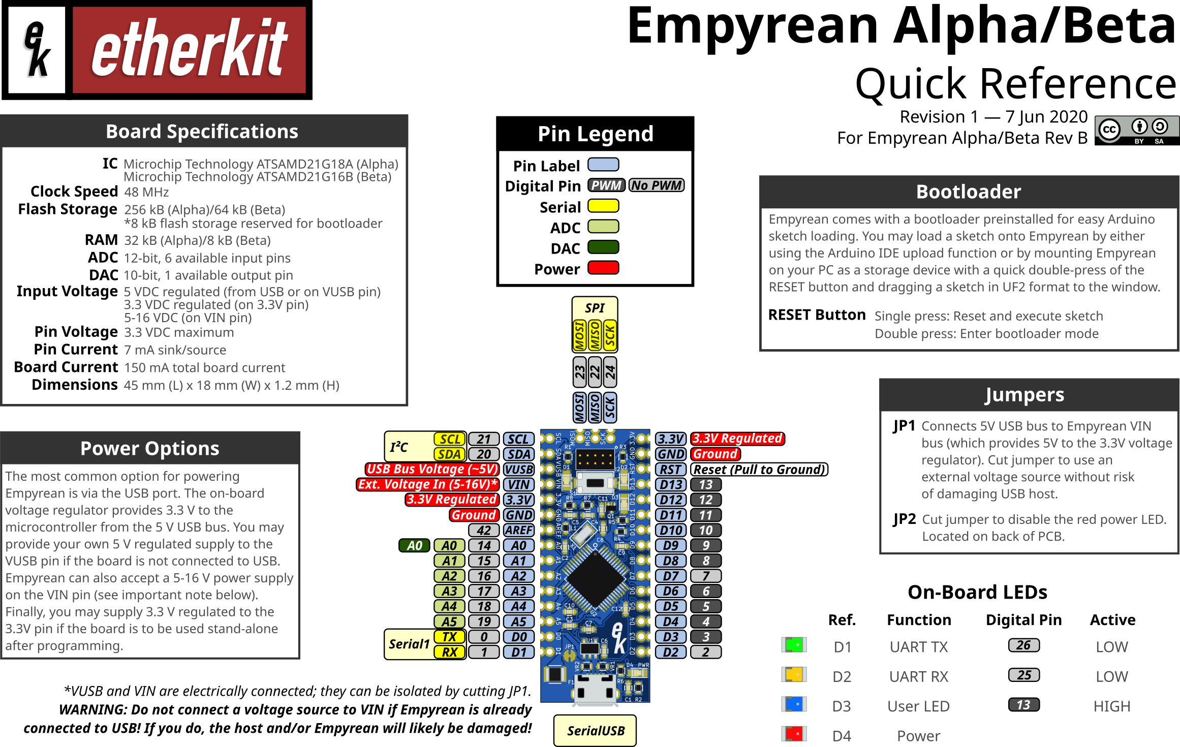
Download a PDF version of the above image here.
Powering the board
The most common option for powering Empyrean is via the USB port. The on-board voltage regulator provides 3.3 V to the microcontroller from the 5 V USB bus. You may provide your own 5 V regulated supply to the VUSB pin if the board is not connected to USB. Empyrean can also accept a 5-16 V power supply on the VIN pin (see important note below). Finally, you may supply 3.3 V regulated to the 3.3V pin if the board is to be used stand-alone after programming.
VUSB and VIN are electrically connected; they can be isolated by cutting JP1.
WARNING: Do not connect a voltage source to VIN if Empyrean is already connected to USB! If you do, the host and/or Empyrean will likely be damaged!
Using the bootloader
Empyrean comes with a bootloader preinstalled for easy Arduino sketch loading. You may load a sketch onto Empyrean by either using the Arduino IDE upload function or by mounting Empyrean on your PC as a storage device with a quick double-press of the RESET button and dragging a sketch in UF2 format to the window.
RESET Button
- Single press: Reset and execute sketch
- Double press: Enter bootloader mode
Onboard Jumpers
JP1
Connects 5V USB bus to Empyrean VIN bus (which provides 5V to the 3.3V voltage regulator). Cut jumper to use an external voltage source without risk of damaging USB host.
JP2
Cut jumper to disable the red power LED. Located on back of PCB.
Using the UF2 sketch format
The UF2 file format for microcontroller firmware is a bit different than the standard Arduino sketch. It is used in conjunction with a specific bootloader (which in installed on Empyrean) to allow firmware to be written to the microcontroller via a simple drag-and-drop operation with a PC’s filesystem. It can be used for everyday programming of a microcontroller board, but excels in being used to distribute a firmware file widely for easy installation and updates by others.
A UF2 file for Empyrean is generated in the Arduino IDE with a special tool. Navigate to the menu item Sketch > Export compiled Binary. The UF2 version of your sketch will be placed in the same output folder where your .ino file is saved. You can upload this firmware to Empyrean by plugging it into your PC and then double-tapping the reset button (pressing it two times in rapid succession). This will place Empyrean into bootloader mode, and it should mount on the PC as a storage device. You can now drag (or copy and paste) your UF2 file to this storage device window to load the firmware into Empyrean. When this happens, the storage device window closes, the firmware loads, and Empyrean resets into sketch execution.
Special pin assignments
| Pin Label | Function | Pin Number |
|---|---|---|
| TX | Serial1 TX | 0 |
| RX | Serial1 RX | 1 |
| A0 | DAC output | A0 |
| AREF | Analog voltage reference | 42 |
| SDA | I2C SDA | 20 |
| SCL | I2C SCL | 21 |
| MOSI | SPI MOSI | 23 |
| MISO | SPI MISO | 22 |
| SCK | SPI SCK | 24 |
Using the built-in USB-Serial UART
When Empyrean is running a sketch and is plugged into a PC via USB, the PC will enumerate this connection as a virtual serial port. You may use this port in your sketch via the standard Serial library by accessing the SerialUSB object.
Using the Serial1 UART
Pins 0 and 1 of Empyrean are also available to be used as a UART via the standard Serial library by accessing the Serial1 object.
Timer Interrupts
Coming soon.