Essential Resources
Arduino IDE Board Support
Repository which hosts the Empyrean support files for the Arduino platform.
GoAbout Empyrean
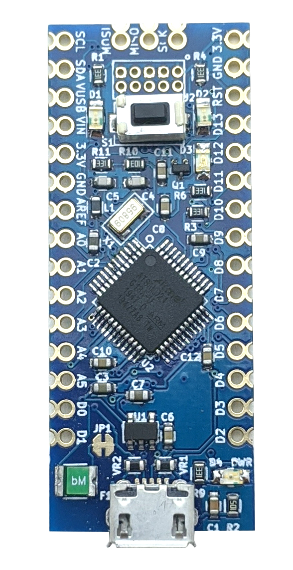
What is Empyrean?
A powerful yet affordable breadboard-friendly Arduino IDE compatible 32-bit microcontroller with ample code space and RAM. Empyrean is derived from the Arduino Zero to be a much more builder-friendly microcontroller which excludes the expensive and rarely-used debug hardware. The PCB has castellated edge pins and a freely-available KiCad footprint for easy integration into larger projects. Empyrean is self-contained when used with a USB connection, as all programming, communication with a host PC (via a virtual UART), and power is provided. Three user-addressable status LEDs are provided on-board, as well as one power LED indicator (which can be disabled with a jumper to save current if desired). Devoted I2C and SPI serial communcation pins are available, as well as a shared hardware UART on digital pins 0 and 1. Six high-resolution (12-bit) ADC pins are included for analog sensing, as well as one 10-bit DAC pin for accurate waveform generation. Nearly every IO pin can be used for GPIO communications in addition to specialty functions that Empyrean provides.
Coding for Empyrean is done with the Arduino IDE. Installing the board support package for Empyrean is quick and simple to do, just see the documentation section below for details. Arduino sketches can be uploaded via the Arduino IDE, as you would typically do with other Arduino-compatible boards. Empyrean also mounts to the PC filesystem as a storage device so that you may load a sketch onto it via a simple drag-and-drop of a specially compiled UF2 file. The Empyrean bootloader itself can also be updated in this way so that you don't have to have a ATMEL-ICE or similar programmer to do this job.
Specifications
- All SMT components assembled, 0.1" headers included unsoldered
- Fully tested
- Four built-in status LEDs: 3 user-addressable and 1 power
- IC: Microchip Technologies ATSAMD21G18A
- Clock Speed: 48 MHz
- Flash Program Storage: 256 kB
- RAM: 32 kB
- ADC: 12-bit, 6 available input pins
- DAC: 10-bit, 1 available output pin
- Input Voltage: 5 VDC regulated (from USB or on VUSB pin), 3.3 VDC regulated (on 3.3V pin), 5-16 VDC (on VIN pin)
- Pin Voltage: 3.3 VDC maximum
- Pin Current: 7 mA sink/source maximum
- Board Current: 150 mA total board current
- PCB material: high quality 1.2 mm double-sided FR4 with soldermask and ENIG coating
- PCB dimensions: 18 mm x 45 mm
- RoHS Compliant