EtherProg is a very simple kit and experienced builders will most likely not need to do anything other than populate the PCB with the correct components and solder in whichever order they desire. This page has detailed assembly instructions for newer builders who would like guidance for the process. Even the experienced builders should pay attention to the cable assembly instructions at the end of this page.
In order to assist with identifying the correct components, the marked values of resistors and capacitors (such as resistor color codes and capacitor numerical markings) will be stated in parentheses after the component’s reference designator (i.e. R1).
It may be handy to print out a copy of the schematics and BOM before beginning your build.
General Component Assembly Instructions
Before getting started, let’s review the ways in which resistors and diodes will be installed in EtherProg. The other components are installed as-is on their PCB footprints. The instructions on assembling the programming cable can be found at the end of these instructions.
Resistors
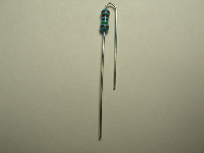
One lead of the resistor/inductor needs to be bent in a U-shape so that it doubles back along the body of the component and is parallel with the other lead. Place the body of the resistor so that the body is over the silkscreened circle. The other lead goes into the hole where the line extending out from the circle points.
Diodes
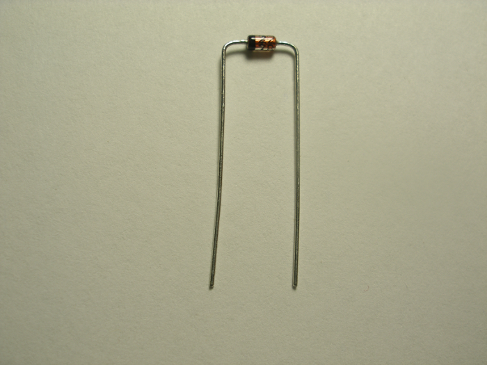
Each diode lead needs to be bent at a 90 degree angle to the body (in the same plane). Diodes are polarized, so be sure that the band (the cathode) on the body of the diode goes on the same end as the band indicated on the silkscreen for that component.
Step 1: Diodes
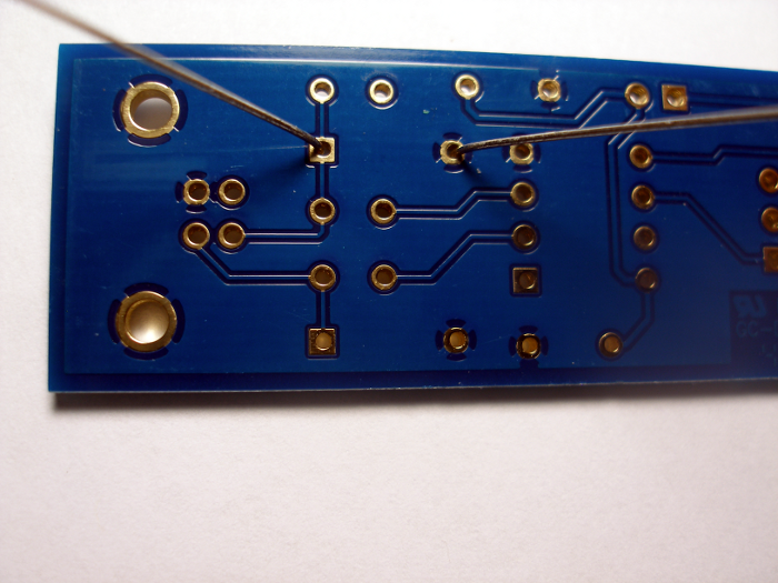
Zener diodes D1 and D2 are identified as small, cylindrical components with red glass bodies and a black banded end. Bend the leads of each diode as specified above and install in the mounting holes indicated on the printed circuit board (PCB).
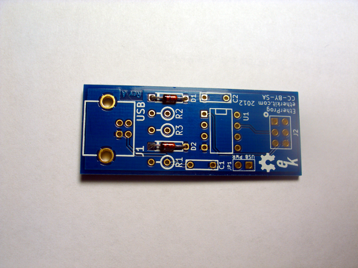
Flip the PCB over and bend the leads of each diode away 45 degrees from perpendicular, solder the leads at the pad on the PCB, then use diagonal cutters to clip the excess leads.
Step 2: Resistors
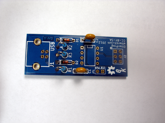
Bend the leads of resistors R1 - 1.5k (brown-green-black-brown-brown), R2 - 68 (blue-grey-black-gold-brown), and R3 - 68 (blue-grey-black-gold-brown) as shown above in the General Component Assembly Instructions. Install in the holes indicated on the PCB, flip the PCB over, and solder the leads just as you did with the diodes.

Step 3: Capacitors
Capacitors C1 - (104) and C2 - (104) are yellow, rounded rectangle shaped components with both leads coming out of one side. They simply fit into the indicated places on the PCB, then are soldered just as the diodes were.
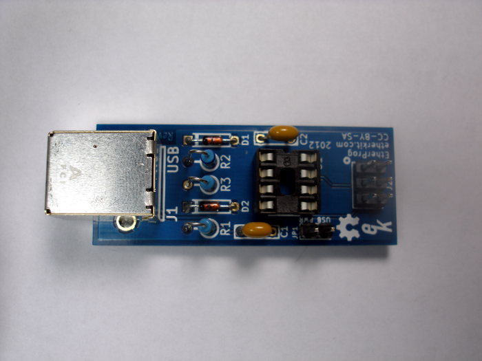
Step 4: IC Socket
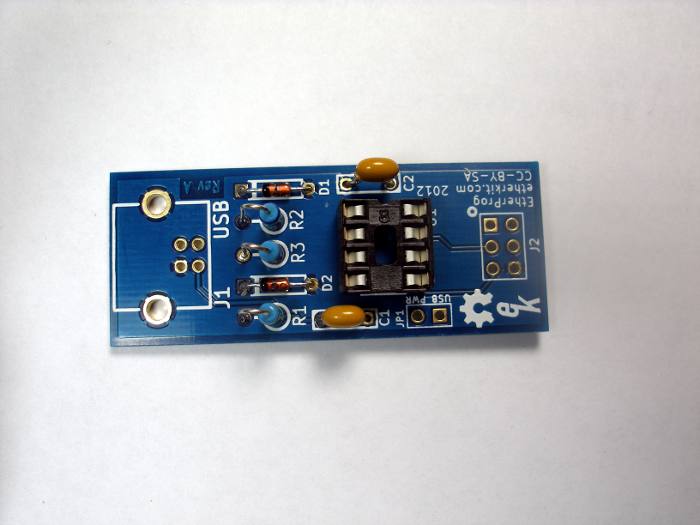
The socket for the ATtiny45 microcontroller is installed in the place indicated for U1 on the PCB. There is a notch in the body of the IC socket to indicate IC polarity. Make sure that this notch is aligned with the notch indicator on the PCB (at the top of the photo below). It can be tricky to solder this socket correctly so that it sits flush to the PCB, so it helps to tack opposite corner pins of the socket first, then check to verify that it is flat against the PCB. If it is not, simple re-heat each solder joint, one at a time, while pushing down on the body of the socket. Once you are sure it is flush, then solder the remaining pins to the PCB.
Step 5: Pin Headers
There are two pin headers on EtherProg: a 2-pin header for providing power to the target device (JP1) and the 6-pin (2 rows, 3 columns) in-system programming header (J2). The strategy for soldering these is similar to the IC socket. Insert the header, then solder one pin (a corner pin on the 6-pin header). Make sure that the header is flush to the PCB (reheat the single solder joint if necessary and readjust the header), then solder the remaining pins.
Step 6: USB Jack
The USB jack (J1) also is installed similarly to the IC socket. Be sure to solder the two large mounting holes as well as the 4 electrical pins. The mounting holes must be soldered for the strength of the USB jack.
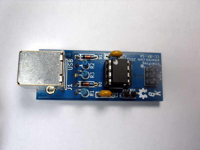
Step 7: ATtiny45
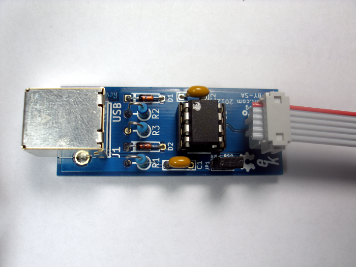
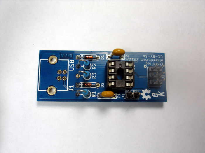
The 8-pin ATtiny45 microcontroller IC now can be fitted into the IC socket. You will likely need to bend each row of legs inwards slightly in order for the IC to fit into the socket. This can be done by grasping all four pins on one side of the IC with needle-nose pliers at the same time, then bending them as a group inwards towards the other row of pins. Repeat this procedure for the other side. Make sure that the side of the IC with the circular indentation on the top is seated on the same side as the notch on the IC socket (top side of the photo below).
Step 8: Programming Cable
Two identical 6-pin IDC sockets are provided, along with a length of 6-pin ribbon cable. Notice that the IDC header has one smooth side and one “keyed” side which has an extruded rail. It will be important to pay attention to these sides in relation to the ribbon cable during assembly.
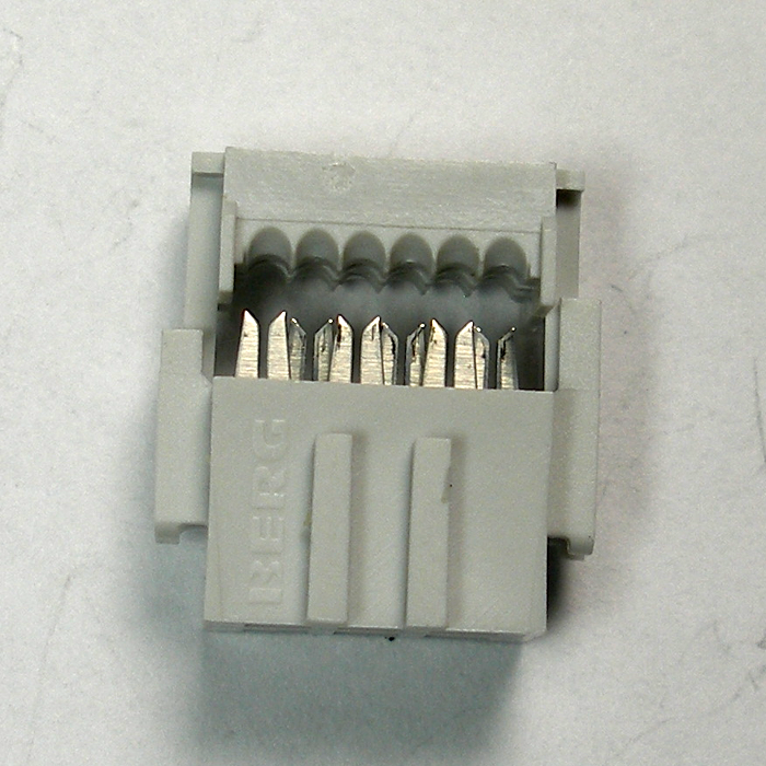
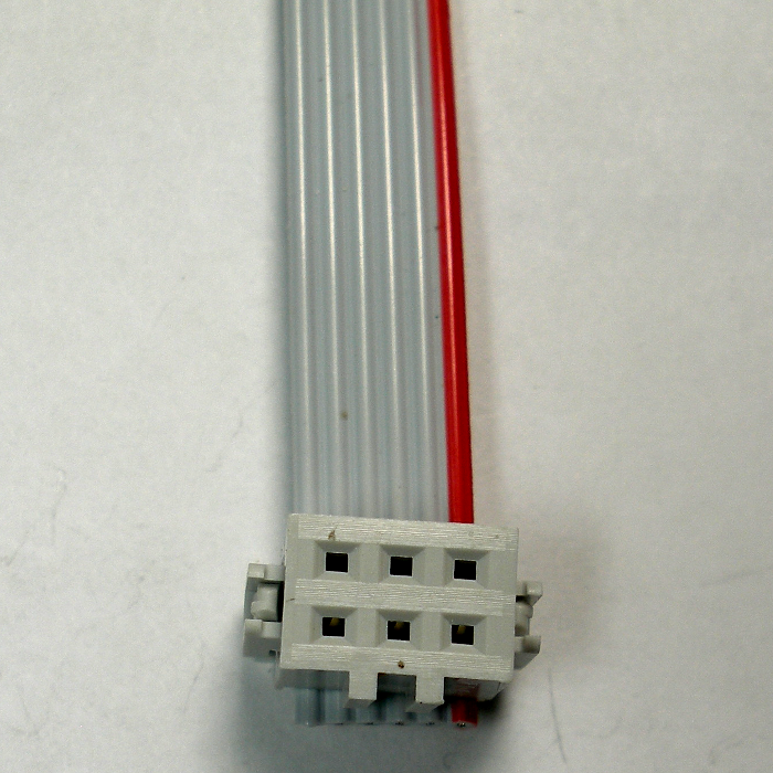
Insert the ribbon cable into one IDC socket so that the end of the cable is on the “keyed” side and that the red striped side of the cable is on the right side when the socket is viewed from the bottom as shown in the photo below. To secure the cable, press down on the top side of the header with a hard, flat object to force the ribbon cable onto the terminals and lock the socket into place. Make sure you can see no gap in the slot where you inserted the ribbon cable. Do not use regular or needle-nose pliers to try to clamp the IDC socket, as you can damage the soft plastic.
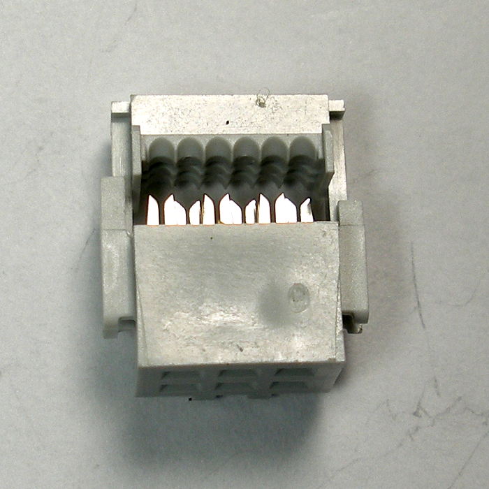
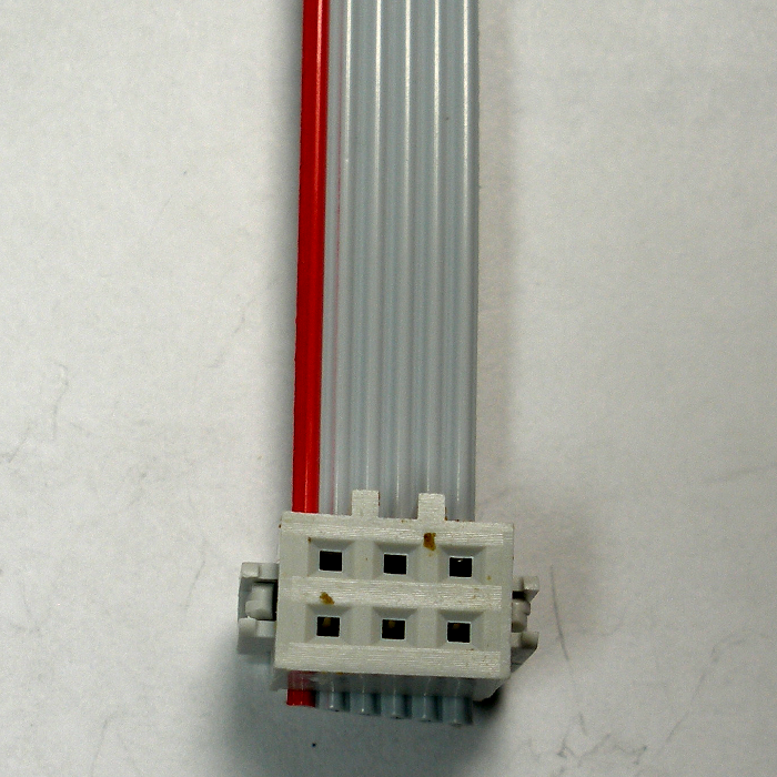
Insert the other end of the ribbon cable into the other IDC socket so that the end of the cable is on the “unkeyed” side and that the red striped side of the cable is on the left side when the socket is viewed from the bottom. To verify that you have this IDC socket oriented correctly, lay the cable so that the IDC sockets have the hole-side up (as shown in the above and below photos). The “keyed” side of each IDC socket should both be on the same sides of each header. Secure the ribbon cable as discussed above.
Install the cable by placing the side of the cable with the “keyed” socket on the outside end of the cable. The red cable stripe goes on the same side as the circle indicated on the PCB just above the 6-pin header. See the photo below for reference.