It is recommended that OpenBeacon be assembled in the order designated below: USB/Microcontroller, Oscillator/Buffer, and Power Amplifier/LPF. This allows for testing of each section to check for the required functionality before moving forward. The marked value for capacitors and resistors will be noted in parentheses after the component value.
It may be handy to print out a copy of the schematics and BOM before beginning your build:
For instructions on how a specific type of component is installed, please see the General Component Assembly Instructions.
If you run into problems with the checks, please refer to the Troubleshooting page.
Microcontroller/USB/Power
- J2 - USB B jack
- 8-pin DIP socket and U1 - ATtiny85
- U2 - 78L05
- Q4 - 2N4403, Q5 - 2N7000
- R1 - 150k (brown-green-black-orange-brown), R2 - 150k (brown-green-black-orange-brown), R3 - 150k (brown-green-black-orange-brown), R4 - 330 (orange-orange-black-black-brown), R10 - 68 (blue-grey-black-gold-brown), R11 - 68 (blue-grey-black-gold-brown), R15 - 1.5k (brown-green-black-brown-brown), R18 - 1k (brown-black-black-brown-brown), R22 - 22k (red-red-black-red-brown), R23 - 22k (red-red-black-red-brown), R24 - 100k (brown-black-black-orange-brown)
- D2 - Green LED, D3 - 1N5227B, D4 - 1N5817, D5 - 1N5227B, D6 - 1N5817, D7 - Red LED, D8 - 1N5817, D9 - 1N5817
- C1 - 100n, C2 - 100n, C9 - 100n, C10 - 100n, C13 - 100n, C17 - 100n
- J1 - 2.1 mm DC (Some of the jacks provided may be a snug fit on the PCB. If you press down very firmly, it will seat flush on the PCB)
- J3 - 2x3 AVR-ISP header
- S1 - pushbutton
Check
Plug a USB A to USB B cable from your PC to J2. Your Linux PC or Mac should automaticaly recognize the OpenBeacon as a USB device.
If you are running Windows, you will need to manually provide the drivers in this ZIP file when prompted for a device driver. Unzip the contents of the ZIP file to a temporary location (it should unpack into a OpenBeaconDriver directory). When Windows states that it cannot find the device driver, choose to manually install the driver, then navigate to the WindowsDriver directory and chose OpenBeacon.inf. If Windows prompts about the driver being unsigned, proceed with the device driver installation any way.
Here’s the quick and dirty Windows installation instructions from the README file:
Open Device Manager (Click Start, and then click Control Panel. Click Hardware and Sound. Click Device Manager.)
Find "OpenBeacon", right-click, select "Update Driver Software..."
Select "Browse my computer for driver software"
Click "Browse...", select the "OpenBeacon Driver" folder which you unzipped, click "OK", click "Next"
"Windows can't verify the publisher of this driver software", select "Install this driver software anyway"
Click "Close"
This is for Windows 7. Older versions of Windows may be slightly different.
On Linux, the command
$ lsusb
should show the device as
16c0:05dc VOTI shared ID for use with libusb
On Windows, the device should be shown in the Device Manager as OpenBeacon under the libusb-win32 category. On OSX you can use the instructions posted here to find the device using the System Profiler.
While plugged into USB, LED D2 should occasionally blink on and off. LED D7 should be constantly lit. This indicates that the FSK drive is working correctly. Remove the USB cable from J2 and connect a 2.1 mm DC power plug with +12 VDC to J1. D2 should light up again as it did with USB connected.
Crystal Oscillator/Buffer
- R5 - 10k (brown-black-black-red-brown), R6 - 10k (brown-black-black-red-brown), R7 - 47 (yellow-purple-black-gold-brown), R9 - 10k (brown-black-black-red-brown), R12 - 10k (brown-black-black-red-brown), R13 - 10 (brown-black-black-gold-brown), R14 - 22 (red-red-black-gold-brown)
- C11 - 100n (104), C14 - 100n (104), C15 - 100n (104)
- L1, L2 (these are molded inductors with green bodies, packaged with the toroid cores), R8
| Band | L1 | L2 | R8 |
|---|---|---|---|
| 80 meters | 22u (red-red-black-gold) | 22u (red-red-black-gold) | 2.2k (red-red-black-brown-brown) |
| 40 meters | 10u (brown-black-black-gold) | 10u (brown-black-black-gold) | 2.2k (red-red-black-brown-brown) |
| 30 meters | 10u (brown-black-black-gold) | 10u (brown-black-black-gold) | 2.2k (red-red-black-brown-brown) |
- C3, C4, C5, C7, C8, C12
| Band | C3 | C4 | C5 | C7 | C8 | C12 |
|---|---|---|---|---|---|---|
| 80 meters | 20 (red trimmer) | 15 C0G (15) | 45 (yellow trimmer) | 150 C0G (151) | 150 C0G (151) | 68 (68) |
| 40 meters | 20 (red trimmer) | 10 C0G (10) | 30 (green trimmer) | 100 C0G (101) | 100 C0G (101) | 68 (68) |
| 30 meters | 10 (blue trimmer) | 3.3 C0G (3R3) | 30 (green trimmer) | 47 C0G (47) | 47 C0G (47) | 47 (47) |
- Q1 - 2N4401, Q2 - 2N4401
- D1 - Red LED
- X1 (Tip: you may wish to use a section 3 pin section of a machined SIP header as a crystal socket if you intend to change crystals. If you do not use a socket, be sure that the case of the crystal is sitting off of the PCB by at least a mm or so. If it is not, the case of the crystal could short out one or both of the pads.)
Check
Apply power through either J1 or J2. If you have on oscilloscope, look for a waveform of the correct oscillation frequency and of approximately 800 mVpp on C15. Alternately, you can use a frequency counter or a receiver to confirm that the oscillator and buffer is working correctly.
If this stage does not function as described, please refer to the Troubleshooting page.
Power Amplifier/Low-Pass Filter
- R16 - 1k (brown-black-black-brown-brown), R17 - 4.7k (yellow-purple-black-brown-brown), R19 - 22 (red-red-black-gold-brown), R21 - 10 (brown-black-black-gold-brown), R25 - 1 (brown-black-black-silver-brown)
- C16 - 100n (104), C18 - 100n (104), C19 - 100n (104)
- C20, C22, C24 (note that C21 and C23 is omitted)
| Band | C20 | C22 | C24 |
|---|---|---|---|
| 80 meters | 820 (821) | 1500 (152) | 820 (821) |
| 40 meters | 390 (391) | 680 (681) | 390 (391) |
| 30 meters | 330 (331) | 560 (561) | 330 (331) |
- R20 - 470 trimmer (471)
- Q3 (BD139)
The front of the transistor is the side with the labeling and the back is the opposite side. The silkscreen indication shows the transistor with the double-line on the back side, so be sure to place the transistor so that the labeling faces towards X1.
- L3, L4 (See Toroidal Inductor Winding Instructions below, consult the following table for number of windings and core type)
| Band | L3/L4 Turns | Wire Length | Core |
|---|---|---|---|
| 80 meters | 28 | 20 in/51 cm | T37-2 (red) |
| 40 meters | 18 | 15 in/38 cm | T37-2 (red) |
| 30 meters | 16 | 12 in/31 cm | T37-2 (red) |
- T1 (cut a length of the red magnet wire to match the length of the green magnet wire, see Bifilar Transformer Winding Instructions below, wind 10 turns on the dark grey core)
- J4 (BNC)
Check
Apply a 50 ohm dummy load to J4 in order to check output power with an oscilloscope or diode detector, or connect J4 to a power meter capable of measuring milliwatt power levels. Apply power thorough J2, then adjust R20 to fully clockwise. With a voltage supply of +13.7 VDC, the output power level should approximately be 300 mW.
If this stage does not function as described, please refer to the Troubleshooting page.
General Component Assembly Instructions
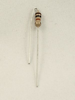
Resistors/Molded Inductors
One lead of the resistor/inductor needs to be bent in a U-shape so that it doubles back along the body of the component and is parallel with the other lead. Place the body of the resistor/inductor so that the body is over the silkscreened circle. The other lead goes into the hole where the line extending out from the circle points.
LEDs
LEDs D1, D2, and D7 have polarity, so be sure to install them so that the flat side of the LED body matches up with the silkscreen outline on the PCB.
Diodes
Diodes are polarized, so be sure that the band (the cathode) on the body of the diode goes on the same end as the band indicated on the silkscreen for that component.
Toroidal Inductor Winding Instructions
The first step in preparing a toroid for installation is to cut some magnet wire to the length specified in the build instructions. If you really want to play it safe (such as if you’ve never wound toroids before), you might want to cut off an extra inch or two to give yourself a safety margin. It’s a bit more painful to unwind the toroid when you run out of wire than it is to clip off some excess.
Put the first turn on the toroid by inserting the wire through the center of the core. Leave about 1 inch of wire on one side of the core, then form the wire so that it wraps firmly around the outside of the core. Take the long end of the wire and place it again through the center of the core, in the same direction as the first turn. Pull the wire through the core and snug it up against the toroid body. Be careful when snugging the wire that you don’t scrape off the wire enamel, which could give you an unexpected short.
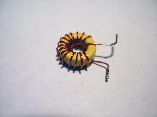
Continue wrapping the wire in this way until you get the desired number of turns. Do not cross the wire over itself during the winding. Remember that each passing of the wire through the center of the core counts as one turn, so the initial placement of the wire is counted as your first turn. Trim off any excess wire length so that both leads are around an inch long. Ideally, there should be about 30° of the toroid not wrapped with wire, so you may need to expand or compress the turns to get the desired coverage of the core. The picture below shows the amount of wire coverage you want on a core.
The magnet wire provided with the OpenBeacon is heat-strippable, so you don’t have to prepare the leads before installing it into the PCB. Place the leads in the holes in the PCB, bend the leads sticking out the back side of the PCB to temporarily secure it to the PCB, then solder the leads to the pads using a medium-sized soldering iron tip. Apply enough heat to the joint to ensure that the heat-strippable enamel coating is burned off the wire and that there is good solder flow from the lead to the pad. Once both leads have been soldered, check that there is 0 ohms resistance between the two pads to ensure good solder joints, then clip the excess wire.
Bifilar Transformer Winding Instructions
A bifilar transmission-line transformer has two identical length windings which are twisted around each other. The first thing to do is to twist together the two pieces of magnet wire. The kit has a length of green magnet wire provided. Cut a piece of the red magnet wire to match the length of the green wire.
There are a couple of different ways to approach the winding. You can manually twist together the wires, which works fine but takes quite a bit of time. An easier way is to use a handheld power drill. Clamp one end of the two wires in a vice or something similar so that they will remain solidly fixed in place. Place the other end of the two wires in the chuck of the power drill, pull the wire taut, and use the drill to do the twisting. Whatever method that you choose, you want to have approximately 8 turns per inch in your wire.
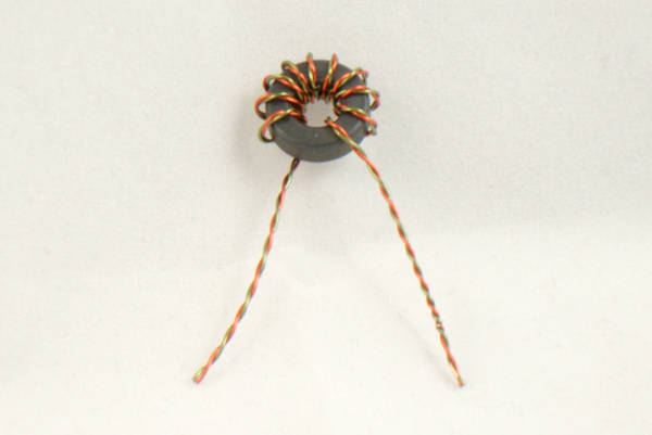
Now that we have our twisted wire, we need to wind it around the core. Clip the rough ends of the twisted wire so that you have tightly twisted ends, then wrap the wire through the core as described in the toroidal inductor instructions above. Trim away the excess so that there is approximately 1 inch of wire left over for each lead. Here is what it should look like at this point:
Now unwind the two windings on each lead, but keep the leads separate from each other, as shown below:
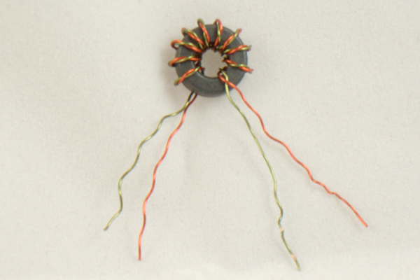
As you can see, there is a red wire and green wire coming from each the left and right sides as a lead. What we want to do is connect the red wire from one side to the green wire from the other side. Take one of those two wires and wrap about three turns around the other wire very close to the core. Solder this joint and snip off one of those wires so that the two together form one lead. This photo shows you what you should have when you are done:
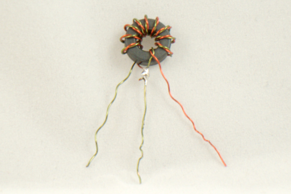
When you install the transformer in the PCB, there is no polarity, but be sure that the lead which was soldered together from the red and green wires is installed in the center hole.