Introduction
Surface mount kit construction is often thought of as difficult, but the average kit builder can handle surface mount construction just as well as through-hole construction as long as he has the proper tools and is shown some methods for dealing with surface mount (SMT) building. There are a few different ways available to the home builder to approach SMT construction, neither of them necessarily better than the other, just different. One approach is to use solder paste (either applied manually or with a stencil), place all of the components at once, then heat them in a DIY reflow oven. That method is a productive way to do things, but requires a bit of up-front investment in equipment. A more practical method for the beginning SMT builder is to approach it as one would a through-hole project, by installing and soldering one component at a time. This is the method which will be presented below.
Tool Selection
Having the proper tools for SMT construction will allow you successfully build a SMT project. Let’s look at the most important tools necessary for your SMT journey.
Soldering Equipment
Every experienced kit builder already had a soldering iron of some kind. The good news is that you probably won’t need to invest in much here. As with through-hole kits, a decent-quality temperature controlled soldering iron is a must. The difference is that you will need a smaller tip for dealing with the smaller parts. Since there is a large variety of soldering irons, you will need to determine the best tip for your particular iron, but we can give some general recommendations. Try getting tips of the smallest size from your soldering iron manufacturer in either a spade or conical shape. You may also want to try the next size up as well, in order to give yourself a bit more heat flow in trade off for maneuverability. For example, the smallest size Weller tips for the WTCPT iron is a 0.062 in/1.52 mm size, which seem to work well in this application.
You will also want to select a small-diameter rosin-core solder for this type of work. A diameter of 0.015” to 0.020” will probably work best. Any larger than that and you will not be able to avoid placing to much solder on a component. Here at Etherkit, we prefer Kester Sn/Pb 0.015” type RMA solder.
Tweezers
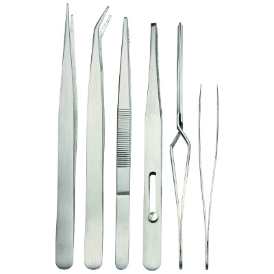
In order to manipulate the small SMT components, you will need some kind of tool. There are small suction pens available, but we have not had much success with them here. The cheapest and most reliable tools, in our opinion, is a set of fine tweezers. Below is a photo of a set of tweezers available from a major discount tool retailer for a very reasonable price. The first two tweezers from the left side (straight and hook-nose) will probably be the best ones to use out of this set, due to their fine points. Shop around and you will find some that fit your construction style.
Magnification and Lighting
Both lighting and magnification are vital for success in SMT construction. There are a few different options for magnification, ranging from a very inexpensive eye loupe to a binocular microscope. Our recommendation for a relatively inexpensive yet decent solution is to use a lighted magnifier (the kind that is usually mounted on an articulated arm). This gives you lots of light and plenty of room to work under magnification. You may also want to go the route of using an eye loupe or a magnifier visor, just be sure that you also have plenty of lighting for your workbench. Regardless of which method you choose, it is imperative to have lots of lighting for your work area; preferably at least two different lights at different angles to prevent deep shadows.
ESD Protection
Many SMT semiconductors are even more susceptible to ESD damage than their through-hold brethern. The MOSFETs and dual-gate MOSFETs in particular are extremely sensitive to low levels of ESD at their gates. Please be sure to use ESD precautions when handling these devices at all times. We recommend at a bare minimum to use an ESD wrist strap while handling components and working on the kit. Working on an ESD mat in conjunction with the wrist strap is even better.
Miscellaneous
Although it is not strictly necessary, we highly recommend using soldering flux when assembling the CRX1. It helps you to achieve consistently good and clean solder joints. A very convenient way to dispense solder flux is via a solder flux pen. Here at Etherkit, we use Kester 951, which is rosin flux, type RMA. A similar, high-quality rosin flux should work great for you.
You may also want to work within a tray such as a cookie sheet in order to contain components from blowing away inadvertently. If you do that, be sure to use an ESD-safe lining for the bottom of the tray. We also recommend only ever taking one SMT component out of its strip at a time, so as to avoid accidents such as sneezing and losing your component in a dust bunny on the floor.
A bit of desoldering braid (such as Soder-Wick brand) can also be a very useful thing to have on hand to clean up mistakes.
General Soldering Technique
The general strategy for this type of SMT construction is similar to the way you build a through-hole project. One component is placed at a time.
The same technique is used for every type of SMT component, which we will outline below.
If you are using flux, add some flux to the component pads. Heat one of the pads with your soldering iron and add a small blob of solder to that pad. Using tweezers, grab your component and prepare to place it on the pads. Heat the pad with solder again using your soldering iron, and keep the iron in place while placing the component on the PCB footprint. This should melt the solder to one of the terminals of the component. Hold the component steady with the tweezers, then remove the soldering iron once you are satisfied that a good solder joint has formed. Once that solder joint is cooled, solder the other component terminal(s). You will want to do this quickly so as not to disturb the first solder joint. One important thing to remember is that SMT components are small and fragile, and it doesn’t take much extra heat to destroy them. Use as little heat as possible in order to get a good solder joint. It won’t take long to get a feel for how much heat you will need once you get started in SMT construction.
Below we have placed some visual examples of installing different types of components. As stated before, the no matter what type of component you are installing, the general principle is the same.
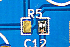
Resistors, Capacitors, and Molded Inductors
Add solder to one pad.
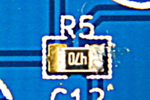
Melt the solder and place the component.
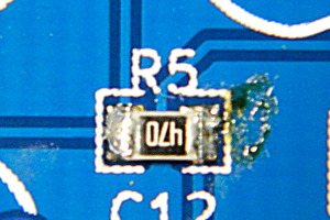
Solder the other terminal.
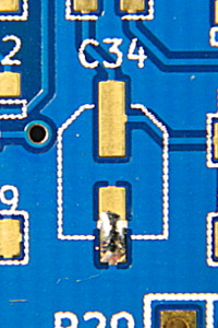
Electrolytic Capacitors
Add solder to one pad.
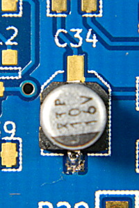
Melt the solder and place the component. Electrolytic capacitors are polarized, so be sure to place the capacitor so that it matches the footprint on the PCB.
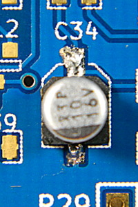
Solder the other terminal.
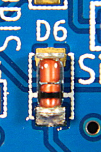
Diodes
Add solder to one pad.
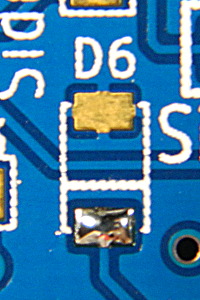
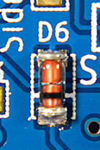
Melt the solder and place the component. Diodes are polarized, so be sure to place the diode so that the stripe on the body is on the same side as the stripe on the PCB footprint.
Solder the other terminal.
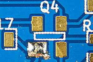
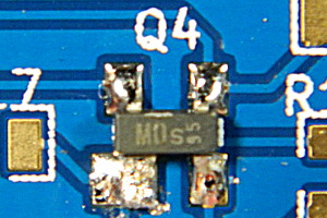
Transistors
Add solder to one pad.
Melt the solder and place the component.
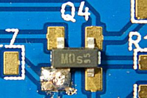
Solder the other terminal(s). This photo shows a dual-gate MOSFET, but other 3-terminal transistors work the same way.
Alternate Resources
If you prefer a more visual tutorial, there is a wonderful free manga-style comic SMT tutorial available here.