Essential Resources
About the Si5351A Breakout Board
What is the Si5351A Breakout Board?
The Silicon Labs Si5351A is a fantastic clock generator IC with some features that you won't see anywhere else. It can generate three independent output signals between 8 kHz and 160 MHz (there are some limitations, see Constraints below), using only a simple 25 MHz crystal reference oscillator. Each output can be independently tuned, switched on or off, and have a variable drive level selected. Using an Arduino and a library provided by us, you may control almost every parameter of the IC. The Si5351A is very useful in a variety of applications, such as wide-range VFOs (and can also simultaneously provide a BFO signal), handy signal source, beacon transmitter, or any other project where a stable and tuneable signal is needed.
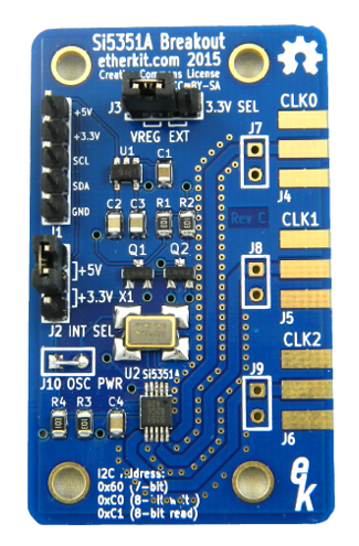
The Etherkit Si5351A Breakout Board makes it convenient to use the Si5351A with your Arduino or other favorite microcontroller. While the Si5351A is a +3.3 V IC, our board provides a low-dropout voltage regulator and level conversion circuitry so that it can be used with either 3.3 V or 5 V controllers. The three outputs are brougt out to pads which accept SMA female end launch connectors (sold separately) and also to 0.1" headers. You may choose a standard 25 MHz crystal reference oscillator, or an optional high-stability 25 MHz TCXO reference oscillator.
Specifications
- All SMT components assembled, 0.1" headers included separately
- Fully tested
- Output frequency range: 8 kHz to 160 MHz (see Constraints below)
- Number of outputs: 3
- Output impedance: 50 Ω
- Output drive levels: 2 mA, 4 mA, 6 mA, 8 mA (into 50 Ω)
- Power supply: +3.3 V or +5 V
- Interface: I2C (on a 0.1" header)
- Output jacks: 0.1" header or optional SMA female end launch
- PCB material: high quality 1.6 mm double-sided FR4 with soldermask and ENIG coating
- PCB dimensions: 30 mm x 50 mm
- RoHS Compliant
Constraints
Two multisynths cannot share a PLL with when both outputs are < 1.024 MHz or >= 112.5 MHz. This means that you may only have two outputs under those conditions.